Hackett
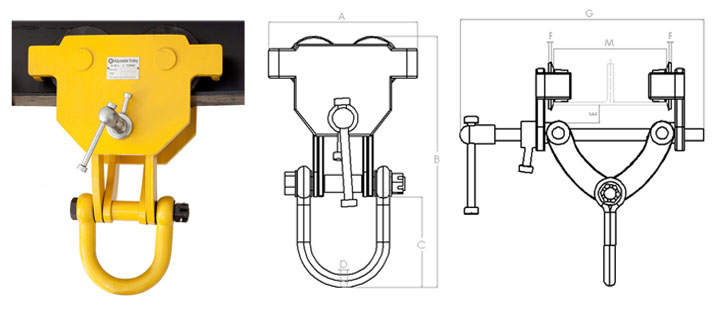
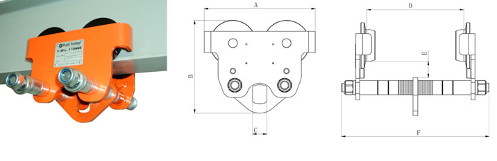
The Hackett Adjustable Trolley offers easy to use attachments for load and lifting requirements. The left and right hand threaded adjustment bar only requires turning so as to ensure appropriate adaption to a beam width, and the trolley is ready to use.
- Fitted with a width adjustment locking mechanism and wheel guarding anti-drop plates
- Easy to install with minimum headroom
- Super quick adjustment to any girder width in range
- Robust all steel construction with safety operation
TECHNICAL SPECIFICATION
|
Part Code |
Size tonnes |
Proof load kN |
Min.Radius of curve m |
Dimensions mm |
Beam Width mm |
Weight kg |
||||||
|
A |
B |
C |
D |
E |
F |
G |
M |
|||||
|
014.100 |
1.0 |
15 |
1.1 |
174 |
263-324 |
105 |
16 |
25.4 |
3 |
340 |
64-203 |
7 |
|
014.200 |
2.0 |
30 |
1.3 |
280 |
339-387 |
111 |
22 |
25.4 |
3 |
340 |
76-203 |
19.5 |
|
014.300 |
3.0 |
45 |
1.4 |
345 |
374-438 |
127 |
27 |
26 |
3 |
345 |
76-203 |
32 |
|
014.500 |
5.0 |
75 |
1.5 |
395 |
450-528 |
135 |
35 |
31 |
3 |
465 |
100-305 |
53 |
|
014.1000 |
10.0 |
150 |
1.9 |
470 |
546-611 |
160 |
40 |
60 |
3 |
488 |
125-305 |
105 |
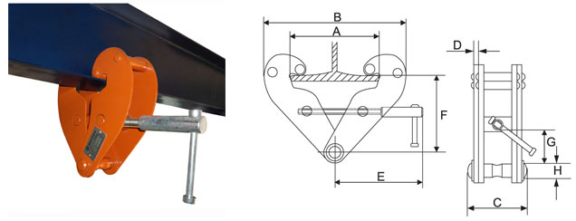
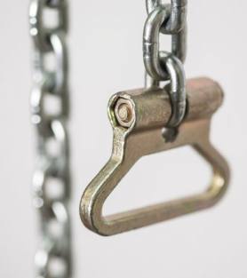
- A quick and easy way to create a hanging point from a eye beam
- Manual chain hoists can be connected to the beam clamp
- The beam clamp is only suitable for lifting vertically at 0.
TECHNICAL SPECIFICATION
|
Part Code |
Size tonnes |
Beam Range mm |
Dimensions mm |
Weight kg |
|||||||||
|
A max |
B min |
B max |
C |
D |
E |
F min |
F max |
G |
H |
||||
|
077.100 |
1.0 |
75-230 |
240 |
192 |
367 |
94 |
4 |
194 |
102 |
154 |
22 |
20 |
4.0 |
|
077.200 |
2.0 |
75-230 |
240 |
192 |
367 |
102 |
6 |
194 |
102 |
154 |
22 |
20 |
4.8 |
|
077.300 |
3.0 |
80-345 |
355 |
243 |
520 |
132 |
8 |
241 |
133 |
223 |
38 |
22 |
9.8 |
|
077.500 |
5.0 |
80-345 |
355 |
243 |
520 |
142 |
10 |
241 |
133 |
223 |
35 |
28 |
11.6 |
|
077.1000 |
10.0 |
90-350 |
360 |
272 |
532 |
180 |
12 |
284 |
155 |
234 |
47 |
38 |
17 |
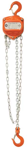
- Proof Load to 1.5 x S.W.L.
- Light Load of 2% of S.W.L.
- Brake Lock Out Test of between 5% - 7% of the S.W.L.
- Endurance Testing Regime EN13157 1500 cycles European JISB8802 2000 cycles Japanese
- Conforms to EN13157 requirements
- Meets European Machinery Directive and is CE marked
- Twin Pawls as standard
- Heavy Duty Forged Safety Catches
- Hook housing is bolt connected using cap head screws and nyloc nut
- All external nuts are nyloc type
- Side Plates are fitted with caged roller bearing
- Zinc plated Pawl Springs
- Load Chain meets the requirements of European and Japanese standards
- Light weight for easy handling
TECHNICAL SPECIFICATION
|
Part Code |
Capacity tonnes |
A mm |
B mm |
C mm |
D mm |
H mm |
Load Chain Size (mm) |
Standard Lift (m) |
Mass Kg |
Extra Weight per Mtr (Kg |
|
022.050 |
0.5 |
130 |
125 |
27 |
32 |
280 |
5.0 x 15 |
3 |
7.8 |
1.4 |
|
022.100 |
1.0 |
155 |
134 |
33 |
40 |
306 |
6.0 x 18 |
3 |
11.1 |
1.7 |
|
022.150 |
1.5 |
173 |
151 |
33.5 |
42 |
368 |
8.0 x 24 |
3 |
15.8 |
2.3 |
|
022.200 |
2.0 |
185 |
157 |
37 |
46 |
445 |
8.0 x 24 |
3 |
16.8 |
2.3 |
|
022.300 |
3.0 |
235 |
157 |
43.5 |
52 |
520 |
8.0 x 24 |
3 |
24.2 |
3.7 |
|
022.500 |
5.0 |
262 |
180 |
51 |
60 |
600 |
10.0 x 30 |
3 |
40.0 |
5.3 |
|
022.1000 |
10.0 |
433 |
189 |
50 |
85 |
800 |
10.0 x 30 |
3 |
80.7 |
9.6 |
|
022.2000 |
20.0 |
630 |
200 |
80 |
110 |
1000 |
10.0 x 30 |
3 |
180 |
19.2 |

|
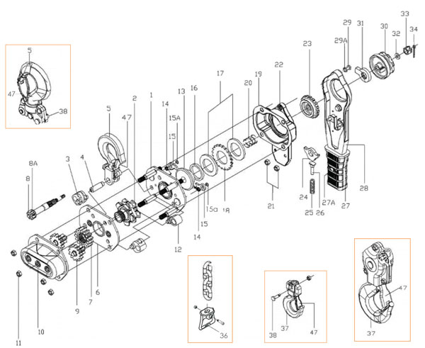
Part Code |
Part Name |
|
C4.01 |
Top Hook Assembly |
|
C4.02 |
Safety Latch Assembly |
|
C4.03 |
Top Hook Shaft |
|
C4.04 |
Bottom Hook Assembly |
|
C4.05 |
Bolt and Nut for Load Chain |
|
C4.07 |
Nut |
|
C4.09 |
Label |
|
C4.10 |
Gear Cover Assembly |
|
C4.11 |
Drive Shaft |
|
C4.12 |
Pinion Gear |
|
C4.13 |
Snap Ring |
|
C4.14 |
Load Gear |
|
C4.15 |
Gear Side PLate |
|
C4.16 |
Stripper |
|
C4.17 |
Guide Roller |
|
C4.18 |
Caged Roller Bearings |
|
C4.19 |
Load Sheave |
|
C4.20 |
Wheel Side Plate Assembly |
|
C4.21 |
Disc Hub |
|
C4.22 |
Brake Disc |
|
C4.23 |
Ratchet Disc |
|
C4.24 |
Pawl Spring |
|
C4.25 |
Pawl |
|
C4.26 |
Snap Ring |
|
C4.27 |
Brake Cover |
|
C4.29 |
Hand Wheel |
|
C4.30 |
Pinion Nut |
|
C4.31 |
Cotter Pin |
|
C4.32 |
Hand Wheel Cover Assembly |
|
C4.33 |
Anchor Bracket |
|
C4.34 |
Split Pin |
|
C4.35 |
Chain Anchor Pin |
|
C4.36 |
Top Hook Pin and Lock Nut |
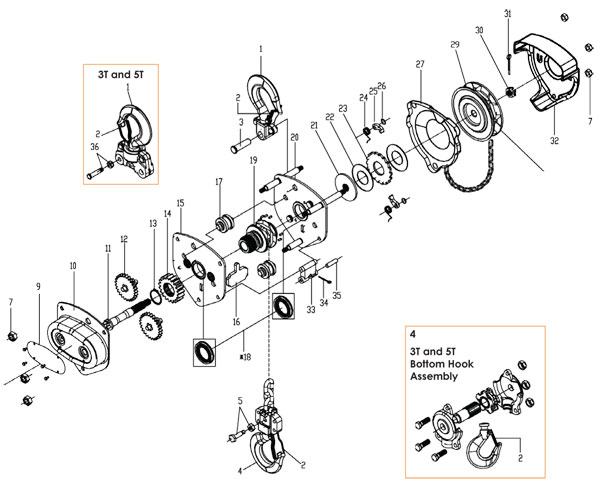
This high quality trolley range is precision engineered in capacities from 500Kg to 10 tonne.
- The trolley enables exact positioning or easy traversing of large loads incorporating manual hoists
- The Hackett series hand geared travel version can be supplied to suit various track widths with the Range 1 and the extended Range 2
- Bottom of the hand chain loop is 500mm from ground level
- Runners (trolley wheels) are precision machined and rotate on maintenance free sealed ball bearings
- Fitted with anti-jump bars
TECHNICAL SPECIFICATION
|
Part Code |
Size tonnes |
Min.radius of Curve |
Dimensions mm |
I-beam recommended mm |
Weight kg |
|||||||
|
Aa |
Ab |
B |
C |
D |
H |
S |
F |
M |
||||
|
055.050 |
0.5 |
0.8 |
270 |
322 |
194 |
176 |
28 |
75 |
30 |
1.5-3 |
50-203 |
10.5 |
|
055.100 |
1.0 |
0.9 |
334 |
436 |
236 |
196 |
32 |
96 |
38 |
1.5-3 |
64-305 |
16 |
|
055.200 |
2.0 |
1.0 |
343 |
445 |
268 |
225 |
42 |
109 |
38 |
1.5-3 |
88-305 |
24 |
|
055.300 |
3.0 |
1.2 |
357 |
459 |
322 |
266 |
52 |
124 |
40 |
1.5-3 |
100-305 |
38 |
|
055.500 |
5.0 |
1.3 |
373 |
475 |
362 |
301 |
62 |
142 |
42 |
1.5-3 |
114-305 |
53 |
|
055.1000 |
10.0 |
2.0 |
406 |
508 |
442 |
396 |
72 |
190 |
45 |
2-3.5 |
124-305 |
94 |
|
055.2000 |
20.0 |
3.5 |
501 |
604 |
555 |
498 |
95 |
233 |
58 |
2-3.5 |
136-305 |
174 |
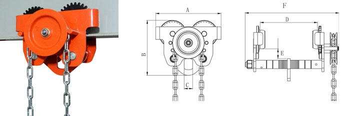
- Positive action brake can hold the load in any position
- Compact light weight and rugged construction
- The brake is sealed in strong steel cover to protect from dust and rain
- Only for pulling
- William Hackett hand winch braking system is fitted with two pawls providing extra safety under all operating conditions
TECHNICAL SPECIFICATION
|
Part Code |
Pulling Capacity (lbs) |
Pulling Capacity (Kg) |
Hand Operated Strength N |
A |
B |
C |
D |
E |
F |
G |
H |
J |
R |
Mass (Kg) |
|
011.120 |
1200 |
550 |
180 |
Ø48 |
Ø134 |
51 |
157 |
Ø27 |
273 |
110 |
156 |
184 |
208 |
3.7 |
|
011.180 |
1800 |
800 |
190 |
Ø60 |
Ø180 |
60 |
190 |
Ø27 |
288 |
110 |
203 |
246 |
319 |
8.1 |
|
011.260 |
2600 |
1180 |
190 |
Ø75 |
Ø180 |
63 |
209 |
Ø27 |
307 |
110 |
216 |
294 |
319 |
10.3 |
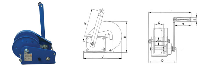
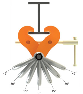
- Fitted with a ‘Gussett’ in both jaws of the beam clamp maximising contact between the beam and beam clamp increasing the grip of the beam clamp
- A shackle is fitted to the bottom of the beam clamp allowing ease of connection of an attached hoist
- The beam clamp can be used to an angle of 45 to the vertical. When the angle is moved away from the vertical the working load limit of the beam clamp needs to be reduced by 50%
TECHNICAL SPECIFICATION
|
Part Code |
Size tonnes |
Beam Range mm |
Dimensions mm |
Weight kg |
|||||||||
|
A max |
B min |
B max |
C |
D |
E |
F min |
F max |
G |
H |
||||
|
017.100 |
1.0 |
75-230 |
240 |
204 |
377 |
119.5 |
5 |
212 |
94 |
149 |
17 |
42.5 |
5.9 |
|
017.200 |
2.0 |
75-230 |
240 |
204 |
377 |
138.5 |
7 |
212 |
94 |
149 |
17 |
50 |
7.5 |
|
017.300 |
3.0 |
100-250 |
260 |
251 |
426 |
165 |
8 |
260 |
169 |
207 |
53 |
57.5 |
12.4 |
|
017.500 |
5.0 |
125-270 |
280 |
263 |
445 |
213 |
10 |
270 |
183 |
224 |
57 |
72.5 |
18 |
|
017.1000 |
10.0 |
130-320 |
330 |
324 |
547 |
267 |
16 |
312 |
192 |
245 |
55 |
91.5 |
36 |


- 1Proof Load to 1.5 x S.W.L.
- Heavy Duty Forged Safety Catches
- Light Load of 2% of S.W.L.
- Hook housing is bolt connected using cap head screws and nyloc nut
- Brake Lock Out Test of between 5% - 7% of the S.W.L.
- All external nuts are nyloc type
- Endurance Testing Regime EN 13157 1500 cycles European
- Meets European Standard Machinery Directive and CE marked
- Conforms to EN13157 requirements
- Load Chain meets the requirements of European and Japanese standards
- Twin Load Chain Guides direct the Load Chain onto the Load Sheave when used in all orientations
- Light weight for easy handling
- Twin Pawls as standard
- All hoist components corrosion protected
TECHNICAL SPECIFICATION
|
Part Code |
Capacity (tonne) |
a mm |
b mm |
c mm |
d mm |
g mm |
h mm |
Load Chain Size(mm) |
Load Chain No.of-Falls |
Mass Kg |
Extra Weight Per Mtr (Kg) |
|
033.075 |
0.75 |
148 |
121 |
37.5 |
265 |
28 |
280 |
5.6 x 17 |
1 |
6.2 |
0.7 |
|
033.150 |
1.5 |
165.5 |
141 |
47 |
415 |
33.5 |
350 |
7.1 x 21 |
1 |
9.6 |
1.1 |
|
033.300 |
3.0 |
194.5 |
178 |
62.5 |
415 |
43.5 |
420 |
10.0 x 30 |
1 |
15.5 |
1.7 |
|
033.600 |
6.0 |
194.5 |
228 |
78 |
415 |
51 |
570 |
10.0 x 30 |
2 |
27 |
3.5 |
|
033.900 |
9.0 |
194.5 |
310 |
- |
415 |
64 |
680 |
10.0 x 30 |
3 |
38.3 |
5.2 |
|
Part Code |
Part Name |
|
L4.01 |
Left Side Plate Assembly |
|
L4.02 |
Load Sheave |
|
L4.03 |
Chain Guide |
|
L4.04 |
Top Hook Shaft |
|
L4.05 |
Top Hook Assembly |
|
L4.06 |
Right Side Plate Assembly |
|
L4.07 |
Load Gear |
|
L4.08 |
Pinion Shaft |
|
L4.08a |
Pinion Shaft Washer |
|
L4.09 |
Pinion Gear |
|
L4.10 |
Gear Cover |
|
L4.11 |
Nut |
|
L4.12 |
Chain Stripper |
|
L4.13 |
Disc Hub |
|
L4.14 |
Pawl Spring |
|
L4.15 |
Pawl |
|
L4.15a |
Circlip |
|
L4.16 |
Bush |
|
L4.17 |
Friction Disc (pair) |
|
L4.18 |
Ratchet Gear |
|
L4.20 |
Spring |
|
L4.21 |
Lock Nut |
|
L4.22 |
Handle Cover Assembly 9inc. 19) |
|
L4.23 |
Change Gear |
|
L4.24 |
Change Over Pawl |
|
L4.25 |
Change Over Spring |
|
L4.26 |
Change Over Stand |
|
L4.28 |
Handle Assembly (inc. 27 + 27a) |
|
L4.29 |
Screw |
|
L4.29a |
Washer |
|
L4.30 |
Grip Ring |
|
L4.31 |
Stop Cam |
|
L4.32 |
Washer |
|
L4.33 |
Castle Nut |
|
L4.34 |
Split Pin |
|
L4..36 |
Square Type End Stop |
|
L4.37 |
Bottom Hook Assembly |
|
L4.38 |
Chain Fixing Pin |
|
L4.47 |
Latch Kit |
This high quality trolley range is precision engineered in capacities from 500Kg to 10t.
- The trolley enables exact positioning or easy traversing of large loads incorporating manual hoists
- The Hackett series push travel trolley can be supplied to suit various track widths with Range 1 and the extended Range 2.
- Runners (trolley wheels) are precision machined and rotate on maintenance sealed ball bearings
- Fitted with anti-jump bars
TECHNICAL SPECIFICATION
|
Part Code |
Size tonnes |
Min.radius of curve m |
Dimensions mm |
I-beam recommended |
Weight kg |
|||||||
|
Aa |
Ab |
B |
C |
D |
H |
S |
F |
M |
||||
|
044.050 |
0.5 |
0.8 |
236 |
286 |
194 |
176 |
28 |
75 |
30 |
1.5-3 |
50-203 |
6.5 |
|
044.100 |
1.0 |
0.9 |
303 |
405 |
236 |
196 |
32 |
96 |
38 |
1.5-3 |
64-305 |
13.0 |
|
044.200 |
2.0 |
1.0 |
317 |
419 |
268 |
226 |
42 |
109 |
38 |
1.5-3 |
88-305 |
20.0 |
|
044.300 |
3.0 |
1.2 |
333 |
435 |
322 |
266 |
52 |
124 |
40 |
1.5-3 |
100-305 |
34.0 |
|
044.500 |
5.0 |
1.3 |
355 |
457 |
362 |
301 |
62 |
142 |
42 |
1.5-3 |
114-305 |
50.0 |
|
044.100 |
10.0 |
2.0 |
378 |
480 |
442 |
396 |
72 |
190 |
45 |
2-3.5 |
124-305 |
89.0 |
|
044.2000 |
20.0 |
3.5 |
449 |
551 |
555 |
498 |
95 |
233 |
58 |
2-3.5 |
136-305 |
167.0 |
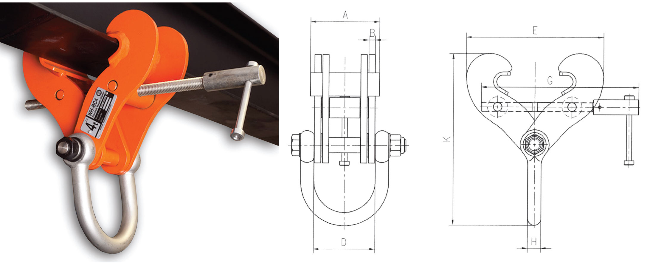
- Fitted with a ‘Gussett’ in both jaws of the beam clamp maximising contact between the beam and beam clamp increasing the grip of the beam clamp
- A shackle is fitted to the bottom of the beam clamp allowing ease of connection of an attached hoist
- The beam clamp can be used to an angle of 45 to the vertical. When the angle is moved away from the vertical the working load limit of the beam clamp needs to be reduced. Please refer to the table opposite - Reduction in working load limits when side loads are applied.
|
Part Code |
Model No |
Size (t) |
Beam Range (mm) |
Dimensions (mm) |
Weight (kg) |
||||||||
|
A |
B |
D |
E max |
E min |
G |
K max |
K min |
H |
|||||
|
027.200 |
WH-BC2 |
2.0 |
76-190 |
130 |
3 |
90 |
254 |
133 |
275 |
263 |
223 |
20 |
4.0 |
|
027.300 |
WH-BC3 |
3.0 |
76-190 |
130 |
12 |
102 |
275 |
166 |
275 |
289 |
251 |
20 |
8.0 |
|
027.300.E |
WH-BC3A |
3.0 |
127-350 |
130 |
12 |
102 |
438 |
228 |
560 |
375 |
294 |
20 |
11.5 |
|
027.400 |
WH-BC4 |
4.0 |
150-254 |
130 |
10 |
112 |
371 |
185 |
410 |
369 |
308 |
25 |
11.0 |
|
027.500 |
WH-BC5 |
5.0 |
76-190 |
130 |
12 |
116 |
306 |
191 |
295 |
338 |
300 |
25 |
10.0 |
|
027.500.E |
WH-BC5W |
5.0 |
150-305 |
130 |
12 |
116 |
422 |
264 |
410 |
413 |
360 |
25 |
15.0 |
|
027.600 |
WH-BC6 |
6.0 |
203-457 |
140 |
12 |
116 |
608 |
267 |
560 |
511 |
402 |
25 |
18.8 |
|
027/1000 |
WH-BC10 |
10.0 |
203-457 |
140 |
20 |
118 |
608 |
267 |
560 |
530 |
421 |
32 |
28.0 |
|
027/1500 |
WH-BC15 |
15.0 |
203-457 |
170 |
20 |
116.5 |
648 |
400 |
660 |
684 |
608 |
40 |
49.5 |
|
027/1500.E |
WH-BC15W |
15.0 |
406-610 |
170 |
20 |
116.5 |
800 |
600 |
810 |
812 |
706 |
40 |
58.5 |
Side loaded across Beam only, as illustrated
REDUCTION IN WORKING LOAD LIMITS WHEN SIDE LOADS ARE APPLIED
|
Angle from Vertical |
0 |
0 to 15 |
15 to 30 |
30 to 45 |
|
Reduction Factor |
Nil |
17% |
34% |
50% |
|
Models |
WLL |
WLL |
WLL |
WLL |
|
027.200 |
2 tonne |
N/A |
N/A |
N/A |
|
027.300,027.300.E |
3 tonne |
2.5 tonne |
2 tonne |
1.5 tonne |
|
027.400 |
4 tonne |
3.3 tonne |
2.6 tonne |
2 tonne |
|
027.500, 027.500.E |
5 tonne |
4.1 tonne |
3.3 tonne |
2.5 tonne |
|
027.600 |
6 tonne |
5 tonne |
4 tonne |
3 tonne |
|
027/1000 |
10 tonne |
8.3 tonne |
6.5 tonne |
5 tonne |
|
027/1500, 027/1500E |
15 tonne |
12.4 tonne |
10 tonne |
7.5 tonne |
The above working load limits and derations have been established specifically for most William Hackett clamps and only apply in overhead beam attachment i.e: DO NOT apply if clamps are to be used for lifting beams.
The tables apply to our clamps only (selected models) and we strongly advise that stress calculations should be carried out (by the user's engineering department) for all support steelwork.
WARNING: All clamps must be correctly applied to the beam by a competent person and fully hand tightened. If in doubt, contact the manufacturer for their recommendations.
NOTE: Clamp model WH-BC (027.200) is not suitable for any side loading as it is of lightweight design.